Eiki LC-SE10 Manuel d'utilisateur
Naviguer en ligne ou télécharger Manuel d'utilisateur pour Projecteurs Eiki LC-SE10. Eiki LC-SE10 User Manual Manuel d'utilisatio
- Page / 60
- Table des matières
- MARQUE LIVRES
- MODEL LC-SE10 1
- Table of Contents 2
- To the Owner 3
- Safety Instructions 4
- AC POWER CORD REQUIREMENT 6
- Compliance 7
- Connecting the AC Power Cord 7
- Features and Design 8
- Part Names and Functions 10
- Installation 16
- Basic Operation 19
- Computer Input 25
- Video Input 33
- Projector mode 42
- Wireless Mouse mode 42
- Maintenance and Cleaning 43
- LAMP HANDLING PRECAUTIONS 46
- Appendix 47
- Projector Condition 49
- USB Key lock 57
Résumé du contenu
MULTIMEDIA PROJECTORMODEL LC-SE10OWNER'S INSTRUCTION MANUAL
10Part Names and FunctionsA built-in micro processor which controls this unit may occasionallymalfunction and need to be reset. This can be done by pr
11Part Names and FunctionsThis projector has control buttons and indicators on its top.To pq wertyuioi LAMP REPLACE indicatorTurns yellow when the lif
12Part Names and FunctionsMUT EPAGEFREEZED.ZOOM NO SHOWONRESET ALL OFFCOMPUT ER 1L ASERFOCUSK E YSTONEZOOMCOMPUT ER 2VIDEOMENUR-CLICKSELECTIMAGEAUTO S
13Part Names and FunctionsMUMUTEPAGEFREEZED.ZOOM NO SHOWONRESET ALL OFFCOMPUT ER 1L ASERFOCUSK E YSTONEZOOMCOMPUTER 2VIDEOMENUMENUR-CLICKSELECTIMAGEAU
14Part Names and FunctionsThis projector has eight different remote control codes (Code 1-Code 8); the factory-set, initial code (Code 1) and the othe
15Part Names and FunctionsTo insure safe operation, please observe the following precautions :● Use (2) AA, UM3 or R06 type alkaline batteries.● Repla
16InstallationProjection angle can be adjusted up to 10.3 degrees with the adjustable feet. Lift the front of the projector and pull the feet lock lat
17InstallationConnecting to a ComputerS - VIDEOUSBUSBCOMPUTER IN 2 /SERVICE PORTCOMPUTER IN 1 DVI - IMCI R - AUDIO IN - LAUDIO IN 1 AUDIO
18InstallationConnecting to Video EquipmentS - VIDEOUSBUSBCOMPUTER IN 2 /SERVICE PORTCOMPUTER IN 1 DVI - IMCI R - AUDIO IN - LAUDIO IN 1 A
19Basic OperationConnect the projector's AC power cord into an AC outlet. ThePOWER indicator flashes red in a moment and turns on red. Press the
2Table of ContentsTRADEMARKS● Apple, Macintosh, and PowerBook are trademarks or registered trademarks of Apple Computer,Inc.● IBM, VGA, XGA, and PS/2
20If a projected picture has keystone distortion, correct the image with KEYSTONE adjustment.Basic Operation• The arrows are white when there is no co
21Basic OperationPress the FREEZE button on the remote control to freeze the pictureon the screen. To cancel the FREEZE function, press the FREEZEbut
22Basic OperationPress the NO SHOW button on the remote control to black out theimage. To restore to normal, press the NO SHOW button again orpress a
23Basic OperationPress the MENU button to display the On-Screen Menu(Menu bar). A red frame is a pointer.Move the pointer (red frame) to the Menu ico
24Basic OperationMenu BarPC System MenuUsed to selectcomputer system.(p26)Image Adjust MenuUsed to adjust computer image. [Contrast / Brightness / Col
25Choose either Computer 1 or Computer 2 by pressing the INPUTbutton on the top control or press the COMPUTER 1 or COMPUTER 2button on the remote cont
26Computer InputThis projector can detect most of the current computer systems with the Multi-scan system and the Auto PC adjustmentfunction provided
27Computer InputAuto PC Adjustment function is provided to automatically adjust Fine sync, Total dots, Horizontal, and Vertical to conform toyour comp
28Computer InputSome computers employ special signal formats which may not be tuned by Multi-scan system of this projector. Thisprojector has Manual
29Computer InputSelect the resolution at the Display area dialog box.Display areaAdjusts the horizontal area displayed by this projector. Press thePo
3To the OwnerCAUTION : TO REDUCE THE RISK OF ELECTRICSHOCK, DO NOT REMOVE COVER (ORBACK). NO USER-SERVICEABLE PARTSINSIDE EXCEPT LAMP REPLACEMENT.RE
30Computer InputPress the MENU button and the On-Screen Menu will appear.Press the Point Left/Right button to move the red frame pointerto the Image S
31Computer InputPress the Point Left/Right but-ton to adjust value.Press the MENU button and the On-Screen Menu will appear.Press the Point Left/Right
32Computer InputThis projector has a picture screen resize function, which enables you to display the desirable image size.Press the MENU button and t
33Video InputChoose Video by pressing the INPUT button on the top control or theVIDEO button on the remote control.Before using these buttons, correct
34Video InputPress the MENU button and the On-Screen Menu will appear.Press the Point Left/Right button to move the red frame pointerto the Input Menu
35Video InputAV System Menu (Video or S-Video)AV System Menu (Component)Press the MENU button and the On-Screen Menu will appear.Press the Point Left/
36Video InputPress the MENU button and the On-Screen Menu will appear.Press the Point Left/Right button to move the red frame pointerto the Image Sele
37Video InputPress the Point Left/Right but-ton to adjust value.Press the MENU button and the On-Screen Menu will appear.Press the Point Left/Right bu
38Video InputThis projector has a picture screen resize function, which enables you to display the desirable image size.Press the MENU button and the
39SettingKeystonePress the MENU button and the On-Screen Menu will appear.Press the Point Left/Right button to move the red frame pointerto the Settin
4Safety InstructionsAll the safety and operating instructions should be read beforethe product is operated.Read all of the instructions given here and
40SettingTerminalThe COMPUTER IN 2/MONITOR OUT terminal on the back of theprojector can be used as computer input or monitor output byswitching Termin
41SettingFor reducing power consumption as well as maintaining the lamp life,the Power management function turns off the projection lamp whenthe input
42SettingThis function is used to reset the lamp replace counter. Whenreplacing the projection lamp, reset the lamp replace counter byusing this func
43The WARNING indicator shows the state of the function which protects the projector. Check the state of the WARNINGindicator and the POWER indicator
44Maintenance and CleaningDisconnect the AC power cord before cleaning.When the projector is not in use, replace the lens cover.132Follow these steps
45When the life of the projection lamp of this projector draws to an end,the LAMP REPLACE indicator lights yellow. If this indicator lightsyellow, re
46Maintenance and CleaningBe sure to reset the lamp replace counter after the lamp is replaced. When the lamp replace counter is reset, the LAMPREPLA
47TroubleshootingBefore calling your dealer or service center for assistance, check the items below once again.– Make sure you have properly connected
48AppendixThis symbol on the nameplate means the product is Listed by Underwriters LaboratoriesInc. It is designed and manufactured to meet rigid U.L
49AppendixCheck the indicators for projector condition. • • • lights green. • • • lights red.• • • off• • • flashes green.✽ When the life of the proj
5Safety InstructionsCAUTION IN CARRYING OR TRANSPORTING THE PROJECTOR● Do not drop or bump the projector, otherwise damages or malfunctions may result
50AppendixMenu TreeSystem (1)MODE 1MODE 2SVGA 1- - - -Auto PC Adj.Fine sync.Total dotsHorizontalVerticalCurrent modeClampDisplay areaDisplay area - HD
51AppendixAutoPALSECAMNTSCNTSC 4.43PAL-MPAL-NVideo InputAuto1080i1035i720p575p480p575i480iStandardCinemaImage 1Image 2Image 3Image 4QuitNormalWide0 -
52AppendixCompatible Computer SpecificationsBasically this projector can accept the signal from all computers with the V, H-Frequency mentioned below
Multi-media Projector53AppendixOwner’s ManualAC Power CordRemote Control and BatteriesDVI-VGA CableUSB Cable Protective Dust CoverLens CoverString for
54AppendixCOMPUTER INPUT/MONITOR OUTPUT TERMINAL (ANALOG)Terminal : HDB15-PIN 51234109 6781514131112Red InputGround (Horiz.sync.)Green InputSense 2Blu
AppendixThe parts listed below are optionally supplied. When ordering those parts, give the name and Type No. to the sales dealer.● MAC Adapter Type
56Attaching the Lens CoverWhen moving this projector or when it is not used for an extendedperiod, replace the lens cover.Thread the string through th
57AppendixUSB Key Lock Function (This is optional function. Optionally supplied USB Key needed.)USB Key lock USB Key lockMove the pointer to itemand t
58Appendix
59Appendix
6ComplianceThe AC Power Cord supplied with this projector meets the requirement for use in the country you purchased it. AC Power Cord for the United
© 2003 Eiki International, Inc.A-key to better communicationsU.S.A.EIKI International, Inc.30251 EsperanzaRancho Santa MargaritaCA 92688-2132U.S.A.Tel
7ComplianceThis projector uses nominal input voltages of 100-120 V or 200-240V AC. This projector automatically selects the correct inputvoltage. It
8Features and DesignThis Multimedia Projector is designed with the most advanced technology for portability, durability, and ease of use. Thisproject
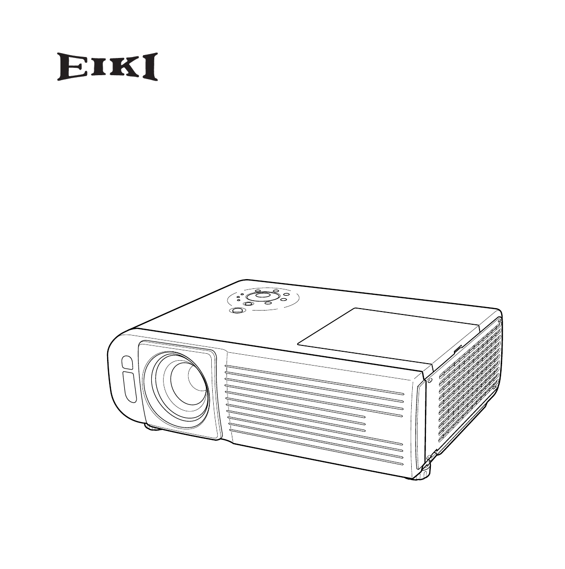
9Part Names and FunctionsBottomBackFrontqwe rtqwerq Adjustable Feetsw Air Filterse Air Intake Vents qewyutyuq Power Cord Connectorw Terminals and Indi
Produits connexes et manuels pour Projecteurs Eiki LC-SE10
 (84 pages)


 (2 pages)
© 2020, manymanuals.fr. Tous droits réservés | 2.618 s |
 Manymanuals.com
 Manymanuals.de
 Manymanuals.fr
 Manymanuals.it
 Manymanuals.pl
 Manymanuals.cz
 Manymanuals.es
 Manymanuals-pt.com
Commentaires sur ces manuels